Automatic Laser Assembly System for Automotive Lidar
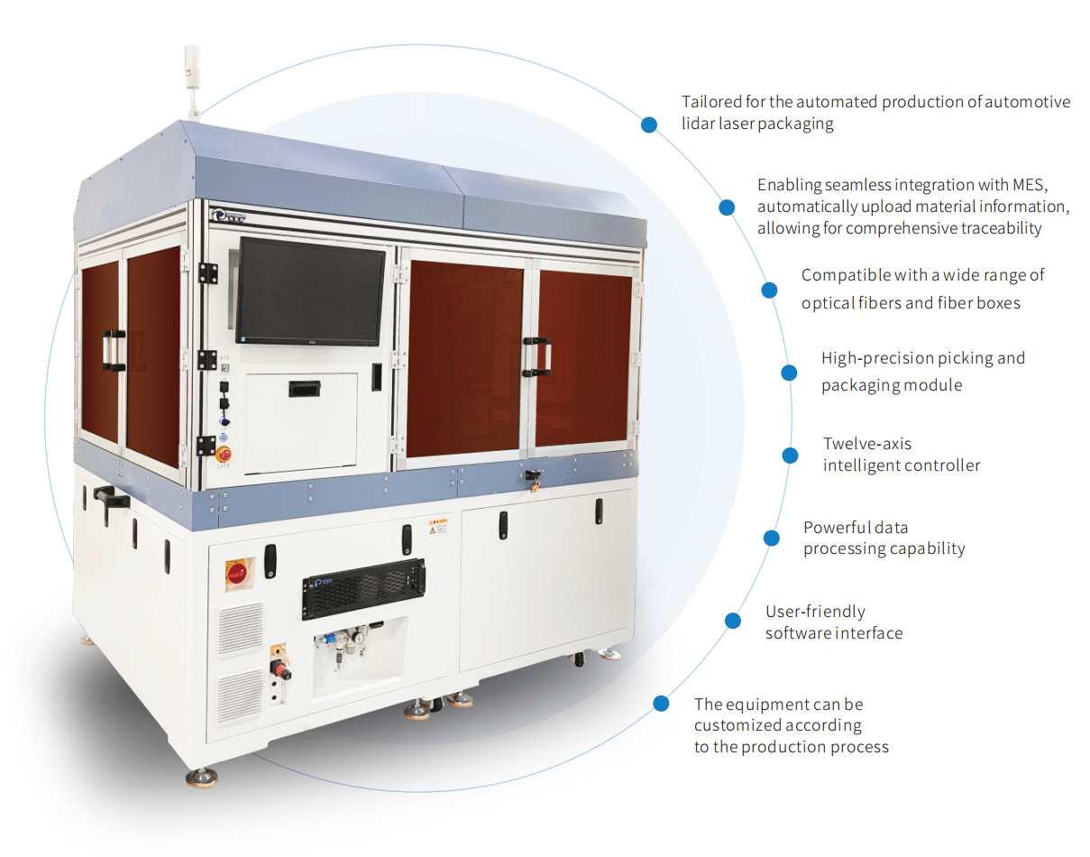
Our company’s independently developed Automatic Laser Assembly System for Automotive Lidar (Model: OA-PA1000L-C00) is designed for automated FC connector insertion into the housing and subsequent adhesive curing. It excels in material identification (Disk fiber and enclosure) and seamlessly integrates program-controlled automatic loading and unloading. The module facilitates ceramic core gripping, de-capping, cleaning, secondary positioning, adhesive dispensing, visual guidance, and curing, ensuring optimal performance.
The comprehensive system comprises a feeding unit, decoding unit, picking unit, de-capping unit, FC connector cleaning unit, secondary positioning unit, visual guidance unit, FC connector unit, dispensing unit, UV curing unit, control unit, and programmable control software. Leveraging advanced visual guidance, the core component precisely inserts the FC connector into the nozzle and end cap of the housing using a bespoke fixture. The process includes UV pre-curing and deep curing to guarantee flawless functionality. The high-precision embedded cast iron module guarantees long-term stability, delivering exceptional motion control and high repeatability. Our ingenious combination of efficient algorithms, proprietary control technology, and dispensing design ensures that the system’s overall performance is on par with imported equipment.

Duration of single-channel connector insertion operation (Including curing process)
| Name | Automatic Laser Assembly System for Automotive Lidar |
| Model | OA-PA1000L-C00 |
| Pressure range | 0.6 ± 0.1 MPa |
| Rated voltage | 220V / 32A |
| Rated Power | 7 KW |
| Power supply | (198~242) VAC,50Hz |
| Vacuum source | -0.07Mpa |
| Network | Cat5/6 |
| Outline dimension | W2000xD1400xH2000mm (excluding the expanded portion of the observation window and the display) |
| Weight | 1500kg |
| Operating environment | Avoid high temperatures and ensure good lighting in the working area Do not expose the equipment to moisture and do not use it in workshops without adequate rain protection measures For indoor use only |
| Equipment structural requirements | The equipment’s structural layout should be reasonable, with no interference between modules, and with sufficient clearance |
| Other requirements | ① The equipment’s design and manufacturing should feature advanced mechanical structure, process manufacturing, control systems, and user-friendly design, while ensuring safe operation ② The necessary standard configuration for the equipment’s normal use must be complete and matching, including all corresponding accessories, cables, tools, and spare parts |

| S/N | Name | Remarks |
| 1 | Ceramic Fiber Optic Retrieval and Placement | The material tray incorporates a clip-based loading mechanism, enabling the production line operator to focus on precisely arranging materials onto the designated tray. Upon completion of material retrieval and placement, the tray smoothly retracts back into the clip-based storage compartment. |
| 2 | Cap Removal Station | Cap Box for Protective Cap Recycling |
| 3 | Fiber Optic Cleaning and Directional Switching | Cleaning and Material Rotation for Ceramic Core Axial Alignment |
| 4 | Enclosure Retrieval and Placement | The material tray incorporates a clip-based loading mechanism, enabling the production line operator to focus on precisely arranging materials onto the designated tray. Upon completion of material retrieval and placement, the tray smoothly retracts back into the clip-based storage compartment. |
| 5 | Vision Positioning Station | After the visual positioning is completed, the enclosure is transferred from the module to the Ceramic Connector Station |
| 6 | Dispensing Station | After securely clamping the ceramic core, the adhesive dispensing mechanism rotates the ceramic surface 360° to ensure precise and uniform adhesive application |
| 7 | Connector and Curing | Once the enclosure is visually aligned, the ceramic connector is inserted into the enclosure using a gripper, enabling UV pre-curing and final curing. |
