Automatic COS Chips Testing System
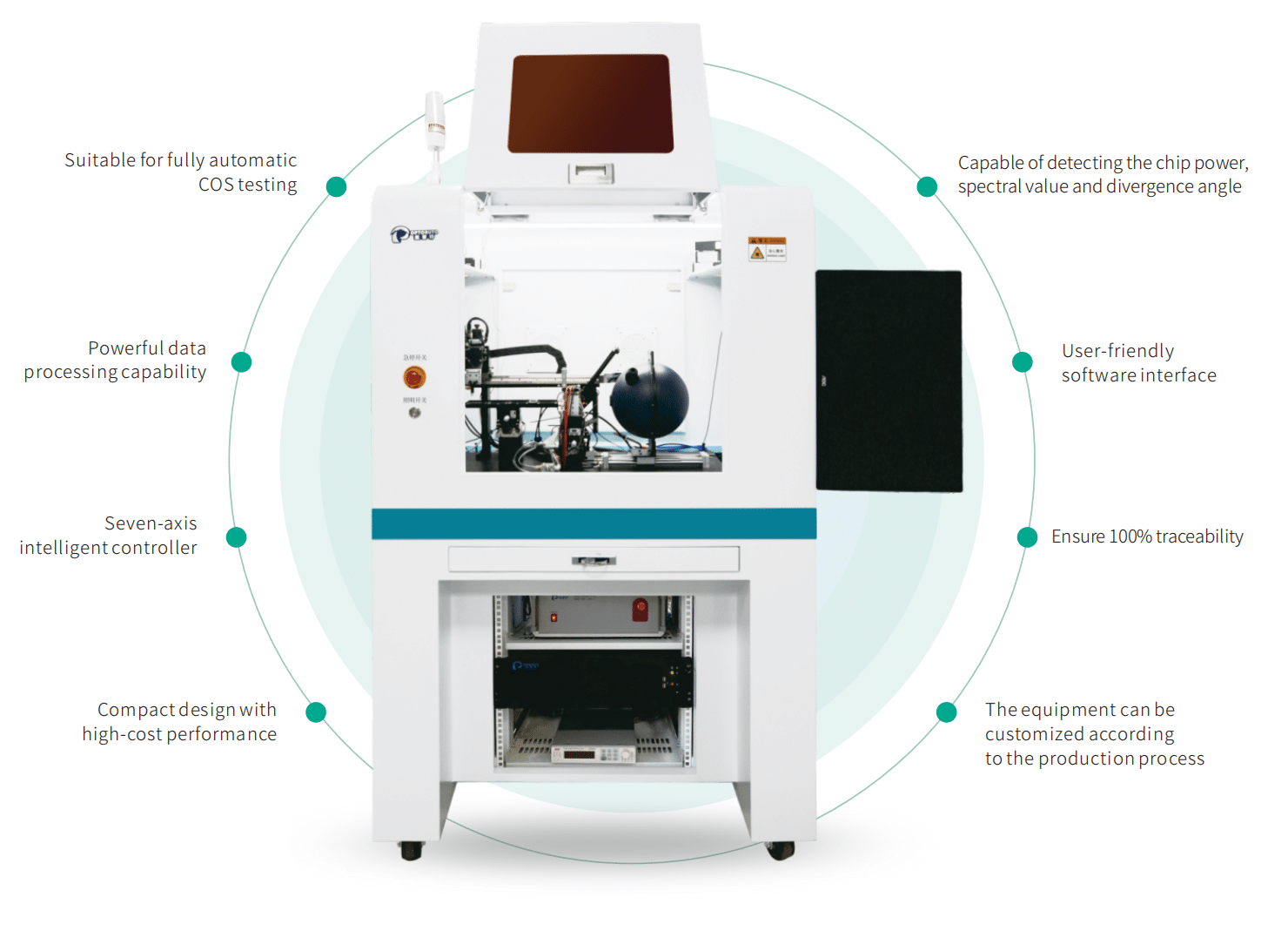
Our company’s independently developed Automatic COS Chips Testing System (Model: OA7000-COS). This system offers full automation for COS chip testing, replacing traditional manual testing. The system enables automatic measurement of luminous power, center wavelength, and fast/slow axis divergence angles.
The system’s primary functional modules consist of automatic feeding, water dispensing, automatic testing and state judgement, water wiping, automated return to the original position or classification box, uploading of relevant data to the database, as well as manual debugging function modules.
The system can be seamlessly compatible with our independently developed fully automatic OCR character recognition system, providing a highly efficient replacement for traditional manual observation and recording through high-magnification microscopes. This ensures 100% traceability for each COS.
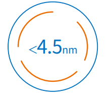
Wavelength differences at varying current levels
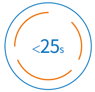
Testing time (under 25A)
| Name | Automatic COS Chips Testing System |
| Model | OA7000 – COS |
| Pressure range | 0.6 ± 0.1 MPa |
| Rated voltage | 220V / 16A |
| Rated Power | 1.8 KW |
| Power supply | (198~242) VAC,50Hz |
| Vacuum source | -0.07Mpa |
| Network | Cat5/6 |
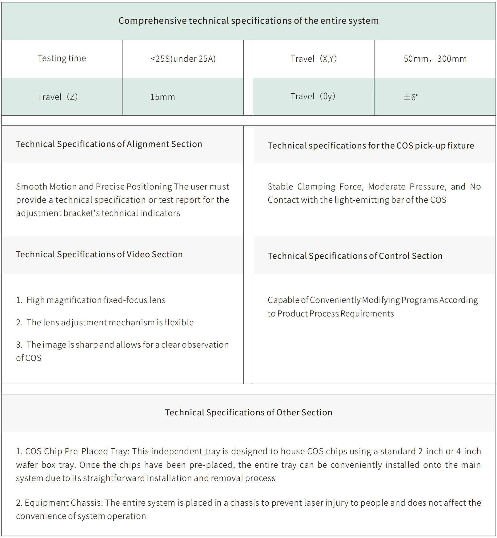
| Outline dimension | W800xD1000xH1685mm (excluding the expanded portion of the observation window and the display) |
| Weight | 270kg |
| Operating environment | Avoid high temperatures and ensure good lighting in the working area Do not expose the equipment to moisture and do not use it in workshops without adequate rain protection measures For indoor use only |
| Equipment structural requirements | The equipment’s structural layout should be reasonable, with no interference between modules, and with sufficient clearance |
| Other requirements | ① The equipment’s design and manufacturing should feature advanced mechanical structure, process manufacturing, control systems, and user-friendly design, while ensuring safe operation ② The necessary standard configuration for the equipment’s normal use must be complete and matching, including all corresponding accessories, cables, tools, and spare parts |
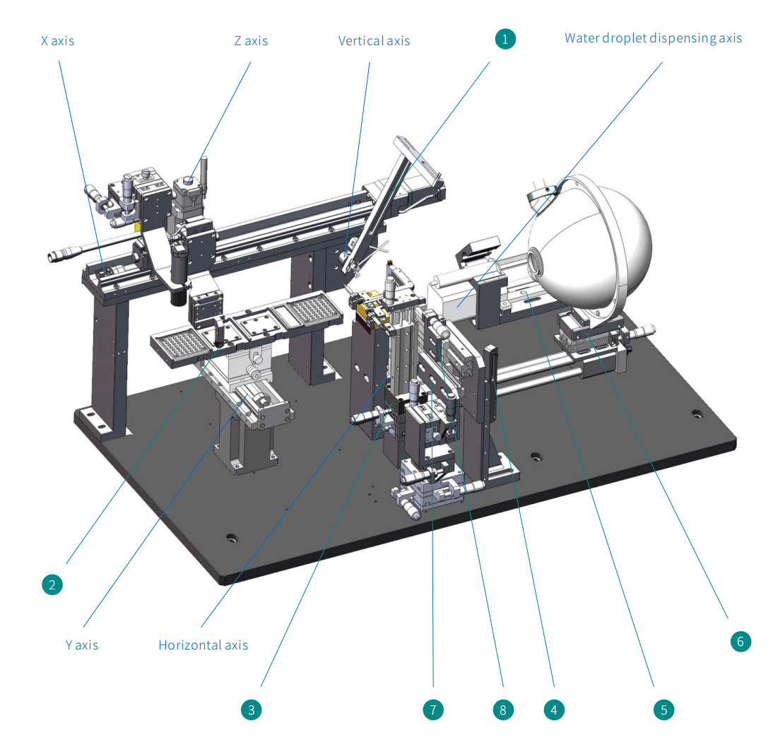
| S/N | Name | Remarks |
| 1 | Rotation arm | Measurement of the chip’s divergence angle (Fast axis) |
| 2 | Material handling fixture | Chip suction |
| 3 | Power-on section | Real-time adjustments to the position of the chips are made using a manual displacement stage for precise alignment |
| 4 | Rotation arm | Measurement of the chip’s divergence angle (Slow axis) |
| 5 | Water droplet dispensing device | Chip heat dissipation |
| 6 | Polarizing ball cylinder | Travel: 30mm |
| 7 | Polarizing mirror | Test the polarization degree of COS |
| 8 | Focusing mirror | Focused light passes through the polarizing mirror |
| 9 | Horizontal axis | Travel: 100°, Positioning accuracy: 0.0072° |
| 10 | Vertical axis | Travel: 100°, Positioning accuracy: 0.0072° |
| 11 | Water droplet dispensing axis | Travel: 70mm, Positioning accuracy: 0.72° |
| 12 | X axis | Travel: 50mm Resolution: {Full/Half: 4μm/2μm, Microstep (1/20 Microstepping) 0.2μm} |
| 13 | Y axis | Travel: 300mm Resolution: {Full/Half: 4μm/2μm, Microstep (1/20 Microstepping) 0.2μm} |
| 14 | Z axis | Travel: 15mm Resolution: {Full/Half: 2μm/1μm, Microstep (1/20 Microstepping) 0.1μm} |
