Automatic Blue-laser Mirror Alignment System
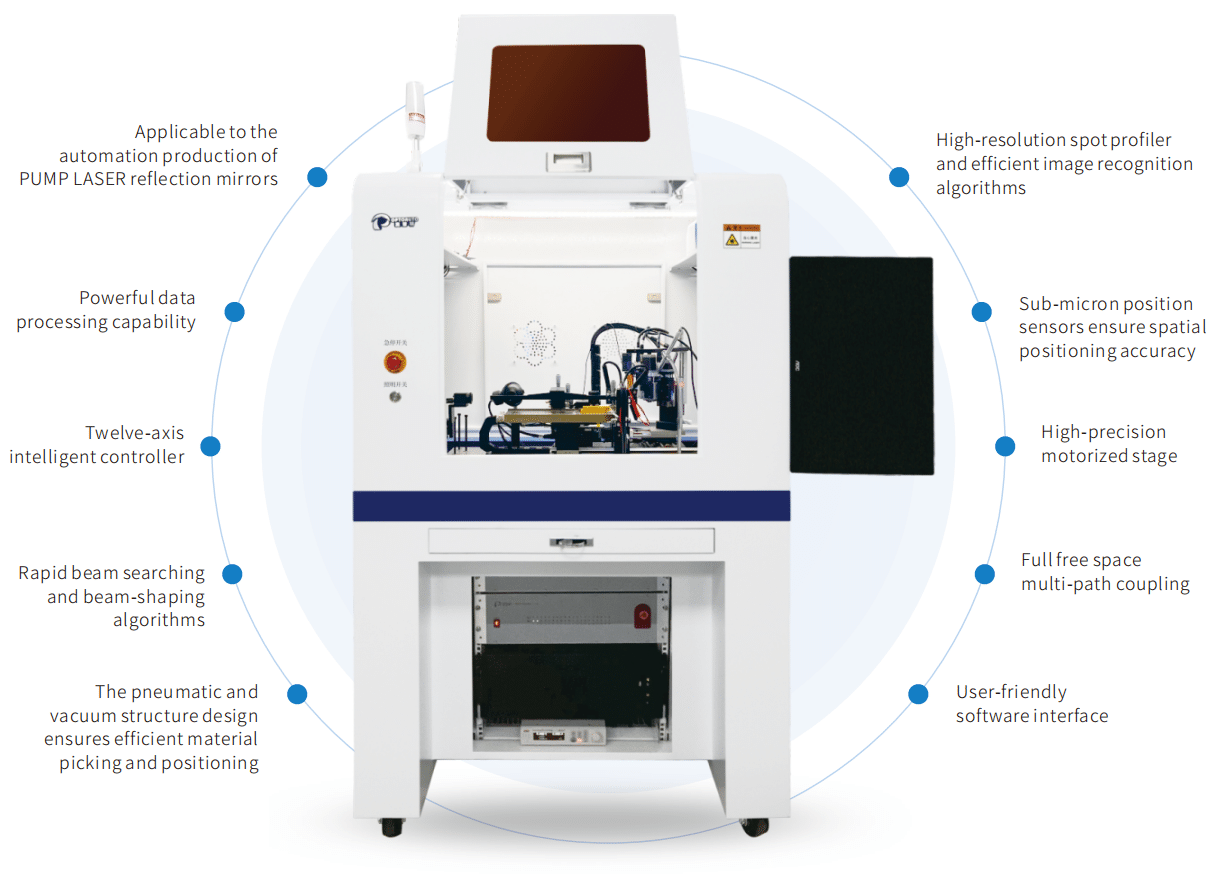
Our company’s independently developed Automatic Blue-laser Mirror Alignment System(Model: OA9000-PBM) is designed for the automated production of array semiconductor fiber-coupled pump lasers. This system can automatically assemble semiconductor laser mirrors and features a pneumatic and vacuum structure design to ensure efficient material handling and positioning. The system employs a high-precision automatic sliding platform to ensure precise movement in six-dimensional space. We offer a twelve-axis intelligent controller and proprietary operating software. Compared with the previous generation OA9000-PLM system, the OA9000-PBM uses collected beam spot images to achieve fully automatic mirror coupling. This automation reduces the need for skilled operators and greatly improves product consistency.
This system comprises a motion unit, automatic dispensing unit, imaging unit, control unit, and programmable control software. The core motion unit features Japanese imported motors with high accuracy and long service life, ensuring long-term stable operation of the system. The combination of efficient image algorithms, our unique control technology, and dispensing design ensures that the system’s comprehensive performance is comparable to that of imported equipment from abroad.
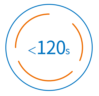
Single-channel coupling time (excluding curing)
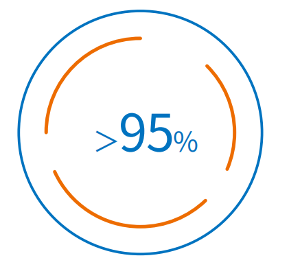
Coupling efficiency
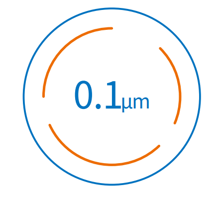
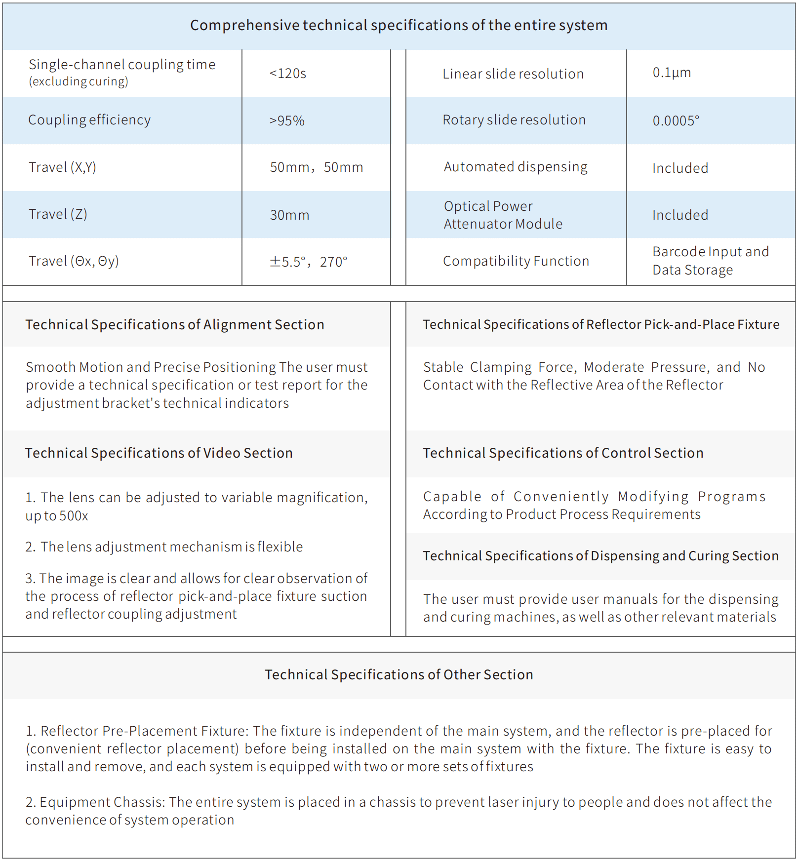
Linear slide resolution
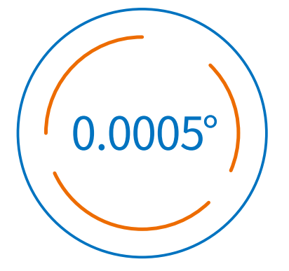
Rotary slide resolution
| Name | Automatic Blue-laser Mirror Alignment System |
| Model | OA9000-PBM |
| Pressure range | 0.6 ± 0.1 MPa |
| Rated voltage | 220V / 16A |
| Rated Power | 1.8 KW |
| Power supply | (198~242) VAC,50Hz |
| Vacuum source | -0.07Mpa |
| Network | Cat5/6 |
| Outline dimension | W800xD1000xH1685mm (excluding the expanded portion of the observation window and the display) |
| Weight | 300kg |
| Operating environment | Avoid high temperatures and ensure good lighting in the working area Do not expose the equipment to moisture and do not use it in workshops without adequate rain protection measures For indoor use only |
| Equipment structural requirements | The equipment’s structural layout should be reasonable, with no interference between modules, and with sufficient clearance |
| Other requirements | ① The equipment’s design and manufacturing should feature advanced mechanical structure, process manufacturing, control systems, and user-friendly design, while ensuring safe operation ② The necessary standard configuration for the equipment’s normal use must be complete and matching, including all corresponding accessories, cables, tools, and spare parts |
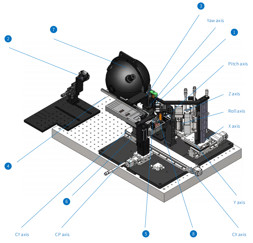
| S/N | Name | Remarks |
| 1 | Near-field CCD | By calibrating the beam spot recognition with dual CCDs, the optimal beam spot can be detected |
| 2 | Far-field CCD | By calibrating the beam spot recognition with dual CCDs, the optimal beam spot can be detected |
| 3 | Automatic dispensing device | The precise dispensing process is carried out smoothly with the help of the Japanese SMC pneumatic slide table |
| 4 | Light guide arm | A set of optical path refraction system is formed by combining precision prism with machined parts to achieve high accuracy |
| 5 | Reflective mirror picking fixture | Sucking the lens and ensuring suction accuracy with an attached sensor |
| 6 | The power-on components | Real-time adjustments to the position of the chips are made using a manual displacement stage for precise alignment |
| 7 | Integration Sphere | Retrieve power reference value |
| 8 | Reflection mirror tray | Position customer’s reflection mirror material |
| 9 | X axis | Travel: 50mm Resolution: {Full/Half: 2μm/1μm, Microstep (1/20 Microstepping) 0.1μm} |
| 10 | Y axis | Travel: 50mm Resolution: {Full: 0.2μm, Half: 0.1μm} |
| 11 | Z axis | Travel: 30mm Resolution: {Full: 2μm, Half: 1μm} |
| 12 | CX axis | Travel: 300mm Resolution: {Full/Half: 2μm/1μm, Microstep (1/20 Microstepping) 0.1μm} |
| 13 | CY axis | Travel: 10mm Resolution: {Full: 2μm, Half: 1μm} |
| 14 | CP axis | Travel: 30mm Resolution: {Full/Half: 2μm/1μm, Microstep (1/20 Microstepping) 0.1μm} |
| 15 | θX (Pitch axis) | Travel: ±5.5°, Repeated positioning accuracy: ±0.003° |
| 16 | θY (Yaw axis) | Travel: 270°, Repeated Positioning accuracy: within ±0.004° |
| 17 | θZ (Roll axis) | Travel: ±6°, Repeated positioning accuracy: ±0.005° |
